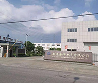
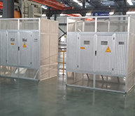
MNS type low voltage draw-out switch cabinet ( hereinafter called switch cabinet) is designed and developed by ourselves, combining with the status of domestic low voltage switchgear. It belongs to new generation of drawer type switch cabinet. Novel structure, compact and reasonable layout, advanced and reasonable component modeling, meet the needs of electric system with AC50-60HZ, 4000A rated current and 660V rated voltage or less, as a controlling equipment of power generation, transport, distribution and change. Thus, switch cabinet is widely used in power plants, substations , factories, mines, petroleum, chemical, high-rise buildings and other power distribution sites.
Product features
● The main frame is molded by pressing C-type aluminum-zinc sheet metal forming, is whole assembly structure. Structure is compact, can operate on the positive side, also can be on the opposite side, protective level of casing is IP3X.
● Each function chamber is isolated from each other, divided into function unit chamber, bus-bar chamber and cable chamber. The role of each chamber is relatively independent.
● Horizontal main bus-bar adopts “laid flat after cabinet ”arrangement method, to enhance the ability of bus-bar’s anti-electric, then aid the main power lines gain the capability of bearing high short-circuit strength.
● Drawers can be designed to 1/4 、1/2、1、2、3, these five standard drawer unit, drawer unit is equipped with mechanical interlock devices. Use high-strength flame- retardant engineering plastics to form, with high security.
Switch cabinet has two outlet types: right outlet and rear outlet
● Don’t need special、complicated tools, easy to install
Normal operational conditions
1, surrounding air temperature
Up limit +40°C (the average value measured over 24h does not exceed 35 ℃)
Lower limit -45°C
2, altitude
not higher than 2500m
3, humidity
the average relative humidity measured over 24h does not exceed 90%;
the average value of water vapor pressure measured over24h does not exceed 2.2kPa;
average monthly relative humidity less than 90%;
the average monthly water vapor pressure not exceeding 1.8kPa.
4, surrounding air is not significantly polluted by dust, smoke, corrosive or flammable gas, vapors or fumes.
5, earthquake intensity does not exceed 8 degrees
Standards
GB7251.1 Low-voltage switchgear and control gear assemblies
Part 1: Type-tested and partially type-tested assemblies
JB/T9661 Low-voltage draw-out switchgear assemblies
IEC439.1 Low-voltage switchgear and control gear
Part 1: Type-tested and partially type-tested assemblies
IEC529 Classification of degrees of protection provided by enclosures(IP CODE)
Basic performance parameter
| Name | Unit | Parameter | ||||||
| Main circuit rated insulation voltage | V | AC660 | ||||||
| Main circuit rated working voltage | V | AC380 | ||||||
| Rated frequency | Hz | 50 or 60 | ||||||
| Bus-bar rated working current | horizontal bus-bar(main) | A | 4000 | |||||
| vertical bus-bar(branch) | A | 1000 | ||||||
| Rated short time withstand electric circuit 1s | horizontal bus-bar(main) | kA | 50,80 | |||||
| vertical bus-bar(branch) | kA | 30,50 | ||||||
| Rated peak vaule withatand current | horizontal bus-bar(main) | kA | 105,175 | |||||
| vertical bus-bar(branch) | kA | 63,105 | ||||||
| Protective level | IP30, IP40 | |||||||
Product structure
The basic structure of the switchgear cabinet is composed by a C profile assembly. C profile plate is made for bending the modulus E = 25mm mounting holes. All frames and inner isolation plates have been treated by galvanized passivated. Surrounding doors and side plates are manufactured with electrostatic powder spraying. For one MCC cabinet, it is mostly installed with thirty-six 8E/4 unit circuits.
Structure of rear outlet MCC cabinet
Main bus-bar is mounted horizontally on top of the switch cabinet, the latter part of the cabinet for cable chamber, inlet and outlet cables are connected in cable chamber located on the rear of cabinet. The front of switch cabinet is equipment small chamber used to install switchgear’s function unit. The system is designed to remove cable chamber on the side of the cabinet to the halt-rear, reducing the width of the switchgear arrangement.
Dimension of outline
| Category | H | B | D |
| Outlet Contact | 2200 | 600 800 1000 1200 | 600 800 1000 |
| MCC | 2200 | 800 1000 | 800 1000 |
| PC | 2200 | 1000 | 1000 |
| Switching | 2200 | 400 | 1000 |
| Capacity | 2200 | 600 800 1000 | 800 1000 |